
Pressure (Hydrostatic)
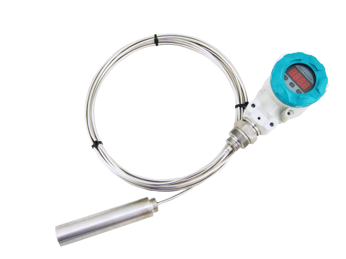
AM-P201 Submersible Level Transmitter with LCD Display
Submersible level transmitter with a local LCD display — the P200 series: 0–200 m, 0.2/0.5 % FS, RS485 and 4–20 mA, IP68.
- Model
- AM-P201
- Category
- Pressure (Hydrostatic)
- Outputs
- 4–20 mA, RS485
- Lead time
- 7–10 working days for standard
- MOQ
-
1 pc
10 pcs for OEM - OEM available
- Yes
A submersible transmitter sits at the bottom of the well and sends its signal up a cable to a panel or a logger a hundred metres away. AM-P201 adds a display in the housing: the same piezo-resistive sensor as the P200, the same 0–200 m range, the same 4–20 mA and RS485 outputs, and the level readable at the well head while the cable is being commissioned or the telemetry is being repaired.
The display does not change what the instrument measures. It repeats the reading the sensor already makes, at 0.2 % or 0.5 % of full scale, and it is worth having only where somebody stands above the well. Where the transmitter hangs in a chamber that floods, or the control room already shows the level on a screen, the P200 is the same instrument without the window. The media limits are the same too: silicon, stainless steel and PTFE against the medium, and pressure under 150 % of full scale.
Technical specifications
| Measuring principle | Piezo-resistive silicon chip on a MEMS process, in a stainless steel housing |
|---|---|
| Range | 0–200 m |
| Display | LCD in the housing (AM-P200: none) |
| Medium | Water, fuel, oil and other liquids |
| Accuracy | 0.2 % FS or 0.5 % FS |
| Over pressure | 150 % FS |
| Operating temperature | −40 to +80 °C |
| Long-term stability | ≤ ±0.2 % FS per year |
| Sensor protection | IP68 |
| Sensor material | SS304, SS316L or PTFE |
| Output | 4–20 mA |
| Communication | RS485 |
| Cable | Vented, for automatic barometric compensation |
| Electrical connection | Red V+, yellow output+ |
Every value above is on the datasheet: AM-P200 and AM-P201 Submersible Level Transmitter Datasheet (PDF · 262.3 KB)
What it is not the answer for
Read this before asking for a price: one of these conditions is what turns a good meter into a bad installation.
- A chamber whose top floods: the display sits in the housing, and a transmitter under water cannot be read
- A site where the level is already on a screen in the control room — the window adds cost and nothing else, and the P200 is the same sensor without it
- Media that attack silicon, stainless steel or PTFE: solvents and strong acids fall outside the wetted material list
- A measuring system where pressure can exceed 150 % of full scale: the overload rating is a limit, not a margin to design into
- A medium above 80 °C, or one that sets on the flush diaphragm: the operating range ends there, and a diaphragm that coats reads low
Where nobody stands above the well, or the housing can flood, the P200 is the same transmitter without the display; where the medium coats the diaphragm, a non-contact radar reads the surface instead.
Maintenance and service life
The diaphragm is the whole instrument: keep it clean and never poke the pressure port with anything sharp. Clean it on the interval your medium sets, because a coated diaphragm reads low long before it fails. Check the desiccant on the vented cable — the reference has to stay open to atmosphere — and compare the local display with the control-room value at every visit.
Behind the instrument
How it is built and tested
Coil winding, the calibration bench, the plant floor — and an overseas customer's factory audit.
What buyers ask before ordering
- What does the display actually show?
- The measured level, in the housing, so it can be read at the well head without a laptop or a call to the control room. The datasheet's P201 column lists the display and nothing else — every other parameter is the series figure shared with the P200.
- Does the display make it more accurate?
- No. Accuracy is 0.2 % or 0.5 % of full scale for the series, whichever build you order; the display repeats the measurement rather than improving it. Long-term stability is quoted at ≤±0.2 % FS per year.
- When can I not read the display?
- When the housing is under water. Sensor protection is IP68 and the cable is made to stay immersed, but a display behind a window has to be above the surface to be read, so a chamber that floods takes the advantage away.
- What supply does it need?
- The datasheet gives the output as 4–20 mA and the communication as RS485, and prints no supply voltage. Send the loop supply or the logger's excitation you have, and we quote the build that matches it.
- P200 or P201?
- Both are the same sensor, cable and accuracy; the P201 adds the local display. Choose it when someone commissions or inspects at the well head, and the P200 when the reading is only needed remotely.
- Which media are out of range?
- The wetted materials are SS304, SS316L or PTFE, and the datasheet's note limits the medium to what is compatible with silicon and stainless steel. Water, fuel and oil are named; a solvent or a strong acid needs the diaphragm checked against it.
Still not sure which version fits your line? Send the medium and the process conditions — we answer with the configuration, not a catalogue.
Applications
Where this model is used
Each application names a measuring point and the conditions that decide the selection.
WW-PS
Pump Station Wet Well Level and Pressure
Wet well level control and rising main pressure for sewage pump stations, where foam and grease blind a non-contact sensor.
WW-WD
Water Distribution District Metering
District metering and pressure management for distribution networks, where night flow and peak demand differ by an order of magnitude.
Elsewhere in the range
Other models in Pressure (Hydrostatic)
The same category holds the models that solve the neighbouring problem, and the price difference is usually smaller than the cost of the wrong principle.
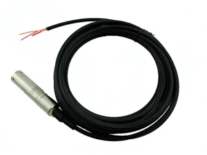
Measuring point does not match the table above?
Send the medium, the pipe size and the output your control system expects. We answer with the principle that fits, or with the reason none of ours does.