
Electromagnetic
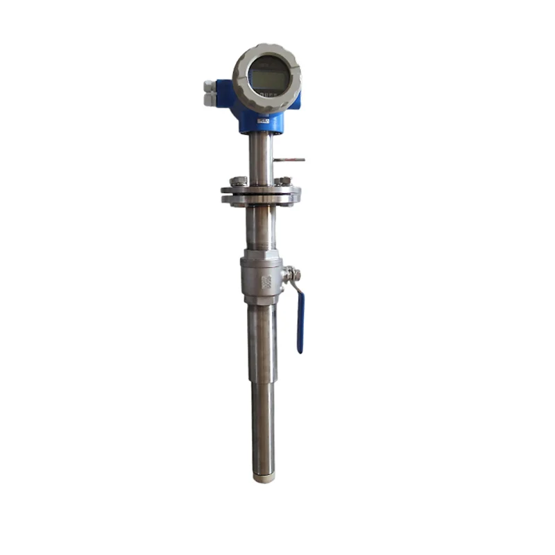
AM-IMFM Insertion Type Electromagnetic Flow Meter
Insertion electromagnetic flow meter for existing large mains, DN300–DN3000 — fitted through a 2-inch ball valve, no pipe cut-out.
- Model
- AM-IMFM
- Category
- Electromagnetic
- Outputs
- 4–20 mA, Pulse, RS485, HART
- Lead time
- 7–10 working days for standard
- MOQ
-
1 pc
10 pcs for OEM - OEM available
- Yes
A full-bore electromagnetic meter needs a spool piece and a shutdown. An insertion meter needs a hole, a 2-inch ball valve and one electrode pushed through to the average-velocity point, which is why it is the instrument of choice when the main is DN300 or larger, already in the ground, and cannot come out for a week.
The trade is accuracy and symmetry. One electrode reads at one point in the velocity profile, so the number depends on where that point sits — 0.25D for the average velocity, 0.5D for the pipe centre — and on the correction factor the datasheet applies to the depth ratio. ±2.5 % is the honest figure, not the ±0.5 % of a full-bore meter; what you buy for it is 5D upstream, 3D downstream, a horizontal run, and a line that only has to come down to 0.2 MPa to be tapped.
Technical specifications
| Measuring principle | Electromagnetic, insertion type: one electrode on a probe at the average-velocity point, fitted through a tapping |
|---|---|
| Line size | DN300–DN3000 |
| Medium | Conductive liquid, conductivity ≥ 50 µS/cm |
| Velocity range | 1–10 m/s, set in the converter |
| Accuracy | ±2.5 % |
| Medium temperature | ≤ 70 °C |
| Maximum pressure | ≤ 1.6 MPa |
| Electrodes | SS304/304L, SS316/316L, Hastelloy, titanium — by medium |
| Probe and head | Probe in SS304 or SS316; head in PVC or F4; through a Φ60×3 mm boss and a 2-inch ball valve |
| Straight run | ≥ 5D upstream and ≥ 3D downstream; control valves at least 3D further downstream |
| Insertion depth | 0.25D for the average-velocity point, 0.5D to the pipe centre |
| Tapping | Φ60–62 mm hole in the pipe wall, welded boss |
| To fit under pressure | Line pressure dropped to ≤ 0.2 MPa |
| Converter distance | Up to 50 m from the probe |
| Output | Current 4–20 mA (load ≤ 500 Ω), pulse (≤ 20 mA), digital communication, HART |
| Power supply | AC 85–265 V or DC 18–36 V |
Every value above is on the datasheet: AM-IMFM Insertion Type Electromagnetic Flow Meter Manual (PDF · 396.2 KB)
What it is not the answer for
Read this before asking for a price: one of these conditions is what turns a good meter into a bad installation.
- Lines smaller than DN300: below that the probe occupies too much of the section and a full-bore meter is the accurate answer
- Media below 50 µS/cm conductivity — deionised water, solvents, oils and gases carry no signal
- Media above 70 °C or a line above 1.6 MPa, which is past the probe's rating
- Vertical downward flow or a line that cannot stay full: one electrode at one point reads what is at that point
- A buried main with no chamber or access above the tapping — the ball valve and the probe head have to stay reachable
- Custody transfer or a ±0.5 % requirement: insertion is a survey instrument at ±2.5 %
Under DN300, under 50 µS/cm, or needing better than ±2.5 %? Then insertion is the wrong form factor — the full-bore electromagnetic meter reads the whole section, and the clamp-on ultrasonic meter needs no tapping at all.
Maintenance and service life
The point of the design is that it can be serviced without cutting the pipe: the probe withdraws through the ball valve. What it needs is the electrode kept clean, since a fouling film is the usual reason a reading falls or wanders, and the insertion depth re-checked after any refit, because 0.25D and 0.5D are different numbers in the converter. Recalibrate when a known flow no longer matches, and state the verification interval your process has to meet when you order.
Behind the instrument
How it is built and tested
Coil winding, the calibration bench, the plant floor — and an overseas customer's factory audit.
What buyers ask before ordering
- Can it be fitted without shutting the line down?
- On a line that can be brought down to 0.2 MPa, yes: the boss is welded on, the ball valve is fitted, and the probe goes through it. Above that pressure the line has to be taken out of service for the fitting.
- Why is it ±2.5 % and not ±0.5 %?
- Because it measures at one point instead of across the whole section: the reading is the velocity where the electrode sits, corrected by the depth ratio β. That is also why the straight run matters more here than on a full-bore meter — five diameters upstream and three downstream is a requirement, not a suggestion.
- How deep do I insert the probe?
- 0.25D puts the electrode at the average-velocity point and is the usual choice; 0.5D reaches the pipe centre. Pick one and set the converter for it — the datasheet's correction factors differ between them, and a probe set to the wrong depth reads consistently wrong.
- Which electrode material do I need?
- SS316L for water and weak acids, Hastelloy C for oxidising and mixed acids, Hastelloy B for hydrochloric acid, titanium for chlorides. SS304/304L is there for the mildest duties. Below 50 µS/cm none of them helps: the medium itself is the problem.
- How far can the converter be from the probe?
- Up to 50 m of cable. Beyond that the signal needs a different arrangement — tell us the distance when you enquire rather than after the cable is pulled.
- What do you need from me to quote?
- Pipe size, wall thickness and material, the medium and its conductivity, the flow range, line pressure and temperature, and whether the line can be brought down to 0.2 MPa to be tapped. The form on this page asks for exactly that.
Still not sure which version fits your line? Send the medium and the process conditions — we answer with the configuration, not a catalogue.
Applications
Where this model is used
Each application names a measuring point and the conditions that decide the selection.
WW-FL
Municipal Wastewater Inlet Flow Measurement
Inlet and outlet flow in raw sewage, where solids, gas entrainment and short straight runs defeat clean-liquid meters.
WW-WD
Water Distribution District Metering
District metering and pressure management for distribution networks, where night flow and peak demand differ by an order of magnitude.
Elsewhere in the range
Other models in Electromagnetic
The same category holds the models that solve the neighbouring problem, and the price difference is usually smaller than the cost of the wrong principle.
Measuring point does not match the table above?
Send the medium, the pipe size and the output your control system expects. We answer with the principle that fits, or with the reason none of ours does.