
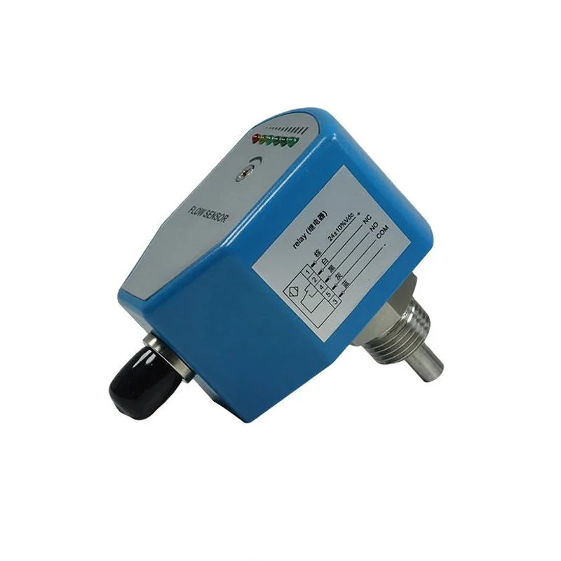
Flow Switch
AM-TFS Thermal Flow Switch
Thermal flow switch for water, oil and air lines: a repeatable contact at a set velocity, PNP/NPN or relay output, IP67 probe.
- Model
- AM-TFS
- Category
- Flow Switch
- Lead time
- 7–10 working days for standard
- MOQ
-
1 pc
10 pcs for OEM - OEM available
- Yes
A thermal flow switch answers one question: is the flow above or below the point I set. Two resistors sit in a sealed probe, one heats and one references; when the flow carries the heat away faster than the setpoint allows, the contact changes. There is no rotor to jam, no paddle to bend and nothing to calibrate beyond turning the potentiometer.
That indifference is what sells it — pneumatic and hydraulic lines, cooling water, cutting fluid, lubricating oil, and pump protection where the flow is either there or it is not. What it cannot do is tell you how much: the datasheet gives velocity ranges (1–150 cm/s in water, 3–300 in oil, 20–2000 in air) and a repeatable contact, not a measurement.
Technical specifications
| Measuring principle | Thermal: a heated and a reference resistor in a sealed probe; the flow carries heat away and the contact trips at the setpoint |
|---|---|
| Velocity range, water | 1–150 cm/s |
| Velocity range, oil | 3–300 cm/s |
| Velocity range, air | 20–2000 cm/s |
| Switching output | PNP, NPN, or relay with normally open and normally closed contacts (SPDT) |
| Contact rating | PNP/NPN max 400 mA; relay max 1 A at 48 V |
| No-load current | ≤ 80 mA |
| Supply voltage | 24 V DC ±20 %, or 230 V AC ±15 % |
| Response time | 1–13 s, typically 2 s; initialisation about 8 s |
| Temperature gradient | ≤ 4 °C/s |
| Setting and indication | Potentiometer setpoint, with a six-LED flow indicator |
| Medium temperature | −20 to +80 °C |
| Ambient temperature | −20 to +80 °C; storage −20 to +100 °C |
| Maximum pressure | 100 bar |
| Probe | 304 stainless standard, 316L optional; 30 mm standard length including thread, other lengths to order; PBT housing |
| Process connection | M18×1.5 female, G1/2 female, G1/4 male, clamp Ø50.5, or NPT1/2 on request |
| Wiring | M12 connector, or 2 m fixed cable |
| Protection | IP67; reverse polarity, short circuit and overload protected |
Every value above is on the datasheet: AM-TFS Thermal Flow Switch Datasheet (PDF · 248.5 KB)
What it is not the answer for
Read this before asking for a price: one of these conditions is what turns a good meter into a bad installation.
- Anywhere you need the value rather than a contact: the datasheet gives ranges and a setpoint, not a flow reading or an accuracy figure
- Media that coat the probe: the switch reads the heat carried away, and a fouling film changes that before anything fails
- Air pockets and sediment on horizontal mounting — the datasheet says to keep the probe away from both
- A hazardous area: no explosion-proof approval appears in the datasheet
- A large pipe at trickle flow: the ranges are in cm/s, so a big line idling below them never reaches the switch's working band
- Custody, dosing or totalising — a switch has no total to give
Need a number rather than a contact? A thermal switch cannot measure — the electromagnetic, ultrasonic or turbine meter gives you the flow and the total, which is what a report, a bill or a mass balance needs.
Maintenance and service life
Wipe the probe when the medium coats it — there is nothing else to service and no calibration to drift. Prove the setpoint after a change of medium or temperature by watching the LED row at a known flow. If it starts tripping early, look at the probe before the electronics: a film on the probe insulates the heater from the flow, which is exactly what the switch is measuring.
Behind the instrument
How it is built and tested
Coil winding, the calibration bench, the plant floor — and an overseas customer's factory audit.
What buyers ask before ordering
- Can it tell me the flow rate?
- It switches. The datasheet gives velocity ranges for water, oil and air, a potentiometer to set the trip point and a six-LED row to show where the flow sits against it — but no flow value and no accuracy figure, because it is not a transmitter.
- Which medium range do I order?
- The ranges are given per medium: 1–150 cm/s in water, 3–300 cm/s in oil, 20–2000 cm/s in air. They are set in centimetres per second, so a large pipe running slowly may sit below the switch's useful range — that is the sizing question to ask first.
- What output do I get?
- PNP or NPN for a PLC input (400 mA maximum), or a relay with one normally open and one normally closed contact rated 1 A at 48 V. Supply is 24 V DC ±20 % or 230 V AC ±15 %, and no-load current stays under 80 mA.
- How is the setpoint adjusted?
- A potentiometer, with a six-LED row showing the flow against the setpoint. Response is 1–13 s and typically 2 s, with about 8 s of initialisation after power-up — so it is not a trip for a fast interlock, it is a guard against a pump running dry.
- What pressure can the probe take?
- The datasheet prints "100 bar" in a row labelled "voltage range", which is plainly a mislabel: the supply is 24 V DC or 230 V AC. We read 100 bar as the pressure rating and confirm it on the order rather than assume.
- What do you need from me to quote?
- The medium (water, oil or air), the pipe size and the flow you consider normal and abnormal, the thread you have — M18×1.5, G1/2, G1/4, clamp or NPT — the output your PLC or relay panel wants, and the temperature at the point. The form on this page asks for exactly that.
Still not sure which version fits your line? Send the medium and the process conditions — we answer with the configuration, not a catalogue.
Applications
Where this model is used
Each application names a measuring point and the conditions that decide the selection.
WW-PS
Pump Station Wet Well Level and Pressure
Wet well level control and rising main pressure for sewage pump stations, where foam and grease blind a non-contact sensor.
WW-IP
Industrial Process Measurement
Flow, level and water quality in chemical, food and pharmaceutical processes, where wetted materials and signal compatibility decide the choice.
Elsewhere in the range
Other models in Flow Measurement
The same category holds the models that solve the neighbouring problem, and the price difference is usually smaller than the cost of the wrong principle.
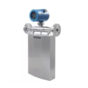
AM-CMFM
AM-CMFM Coriolis Mass Flow Meter
Coriolis mass flow meter that reads mass, density and temperature from one tube — DN1–DN150, for dosing and recipe lines.
AM-D-DFM
AM-D-DFM Doppler Flow Sensor
RS485 Doppler flow sensor, not a meter: 0.03–5 m/s velocity, 0.05–10 m level, 7.2–15 V DC, for a host to compute flow.
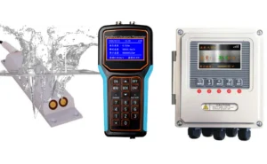
AM-DFM
AM-DFM Doppler Flow Meter
Doppler flow meter for channels, manholes and partly filled pipes: surface velocity plus water level, no weir or flume required.
Measuring point does not match the table above?
Send the medium, the pipe size and the output your control system expects. We answer with the principle that fits, or with the reason none of ours does.